
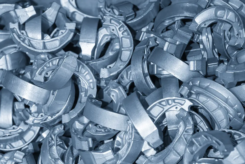
The parting line is one of the first features engineers consider when designing a mold, since it affects everything from pattern creation to casting quality. It marks where the two mold halves meet and separate, allowing the finished casting to be removed after the metal solidifies.
While the seam left behind may appear minor, its location has a direct impact on mold design, dimensional accuracy, finishing requirements, and the likelihood of defects (e.g., flash or mismatch). In shell molding and iron casting, where consistency and precision are a must, selecting the right parting line early in the design process helps improve repeatability and reduce unnecessary production costs.
A properly planned parting line in casting helps manufacturers:
- Allow mold halves to separate cleanly
- Support accurate pattern and core design
- Reduce flash and mold mismatch
- Improve dimensional consistency
- Minimize finishing and machining
- Produce more repeatable, high-quality castings
Definition and Purpose of Parting Lines
Parting lines result from dividing a mold into two or more sections. The mating surfaces themselves are known as the parting surface, while the visible seam left on the finished casting becomes the parting line. Without this separation, removing a solidified casting would be nearly impossible for many part geometries.
Why the Mold Must Separate
Every mold needs a way to release the finished casting. Dividing the mold into sections allows each half to move away from the casting after cooling. This separation protects both the mold and the casting from unnecessary damage during removal and makes high-volume production practical: molds can be opened and cleaned, then prepared for the next cycle efficiently.
Pattern Design and Draft Angles
Parting line placement also affects pattern creation. Designers must account for draft angles that provide slight tapers, allowing the pattern to be withdrawn from the mold without tearing or damaging the mold cavity. Choosing the wrong parting line often requires larger draft angles or more complicated tooling. Complex parts may also require cores to create internal cavities. In these situations, the location of the parting line influences core placement and core support, along with overall mold assembly.
For shell molding, where tight tolerances are expected, these relationships become especially important, since small tooling errors can affect every casting produced.
Impact of Parting Line Location on Casting Quality
The location of the parting line affects more than appearance. It influences dimensional accuracy, mold alignment, metal flow, cleanup time, machining requirements, and even production costs. When positioned strategically, the parting line blends naturally into the geometry of the component. But poor placement can introduce defects that increase scrap or require additional finishing.
Common Quality Issues
Poor parting line placement or mold alignment often leads to several casting defects. One of the most common is flash, a defect that occurs when molten metal escapes through the small gap between mold halves. While flash can usually be removed, it adds labor and increases finishing costs. Mismatch is another concern. If mold halves shift slightly during assembly, the casting surfaces no longer align perfectly, leaving an offset that may require machining or cause dimensional problems.
Other issues include:
- Excessive flash requiring additional grinding
- Mold mismatch affecting dimensions
- Surface irregularities along the seam
- Increased machining requirements
- Visible cosmetic imperfections
- Reduced consistency between production runs
Surface Finish and Tolerances
Parting line location can also affect where machining stock is required and whether visible surfaces remain free from noticeable seams. Engineers often position the parting line where minor finishing marks will have minimal impact on function or appearance. In some cases, relocating the seam a small amount can dramatically reduce finishing work.
Techniques for Determining Optimal Parting Line Placement
There isn’t just one formula for choosing the best parting line. Instead, engineers weigh several factors at the same time to find a location that supports both manufacturability and finished part quality. The goal is straightforward: create a mold that fills properly and releases the casting cleanly to minimize the need for secondary operations.
Start With the Part Geometry
The starting point is usually the component’s geometry. Designers look for natural dividing points that allow the mold halves to separate without creating unnecessary undercuts or overly complex tooling. Flat surfaces and symmetrical features often make good candidates, but more intricate parts may require curved or stepped parting surfaces that better follow the shape of the casting.
Draft angles are another important consideration. Providing the proper taper helps patterns release from the mold without damaging the cavity. If internal passages or hollow sections are needed, engineers also evaluate how to position and support cores. These decisions are closely connected, so changing the parting line may also require adjustments to the pattern and gating system, along with the core design.
Balance Metal Flow and Manufacturing Requirements
Engineers evaluate how molten metal will move through the mold, looking for a parting line that promotes smooth filling while helping reduce turbulence, air entrapment, and the likelihood of casting defects. They also consider:
- Which surfaces require machining
- Which features will remain visible
- Where tight dimensional tolerances are most important
Keeping the seam away from these areas can reduce finishing time while improving both appearance and overall quality.
Use Simulation to Refine the Design
Modern foundries increasingly rely on casting simulation software to validate these decisions before tooling is manufactured. Digital modeling allows engineers to predict filling patterns and solidification behavior, along with potential problem areas, before production begins. For shell molding, in particular, this technology reduces trial-and-error and helps optimize tooling, while also supporting more consistent iron castings throughout long production runs.
Parting Line Optimization Across Different Casting Methods
Although every mold-based casting process relies on a parting line, the way engineers approach its placement depends on how the mold is made and what the process is designed to accomplish. Each casting method presents its own balance of precision, production speed, tooling complexity, and finishing requirements.
Shell Molding
Shell molding is known for producing iron castings with excellent dimensional accuracy and surface finish. Since the tooling is manufactured to tight tolerances, engineers invest considerable effort in selecting the best parting line before production begins. Careful planning helps reduce flash and simplify finishing, maintaining consistent quality across high-volume runs.
Sand Casting
Sand casting offers greater flexibility for larger or more complex components, but it also requires careful attention to mold alignment. Since the mold is formed from compacted sand (rather than being a permanent metal mold), the parting line needs to support reliable assembly while minimizing the potential for mismatch or excessive flash. Designers often balance ease of molding with downstream machining and finishing requirements.
Die Casting and Investment Casting
Processes such as die casting and investment casting bring their own design priorities. High-volume die casting requires parting lines that allow steel dies to open efficiently while maintaining dimensional accuracy. Investment casting can produce highly detailed components with very subtle seams, but engineers still evaluate mold separation carefully during pattern development to ensure the casting can be produced reliably.
Despite these differences, the objective remains the same across every casting method: place the parting line where it supports efficient production and minimizes defects in order to deliver the required level of quality with as little secondary work as possible.
Common Challenges and Solutions in Managing Parting Lines
Even with careful engineering, parting line issues occasionally arise during production. But many of these problems can be identified early and corrected before they affect large production runs. Regular tooling inspections and process monitoring, along with communication between design and production teams, all contribute to better outcomes. Some of the most effective practices include:
- Inspect tooling regularly for wear or damage
- Verify mold alignment before each production run
- Monitor flash levels as part of routine quality inspections
- Review parting line placement during new product development
- Use simulation to evaluate design changes before tooling modifications
- Incorporate finishing requirements into early design decisions
Finishing processes remain an important part of quality control as well. Grinding, trimming, shot blasting, and machining remove excess material, surface scale, and other imperfections that remain after casting. But relying too heavily on finishing can increase labor costs and extend production schedules. Whenever possible, manufacturers aim to solve problems at the mold design stage rather than after the casting has been produced. Continuous improvement efforts often focus on identifying recurring issues, updating tooling, refining process controls, and sharing lessons learned across engineering and production teams.
Better Parting Line Design Leads to Better Castings
A well-designed parting line supports nearly every stage of the casting process. From pattern creation and mold assembly to quality inspections and finishing, its location affects efficiency and consistency, along with the final performance of the component.
Manufacturers that invest time in optimizing parting line placement often see improvements in casting quality, lower scrap rates, reduced finishing costs, and more predictable production. Mold design that combines modern simulation tools and experienced engineering with disciplined quality control helps deliver dependable results, from prototype through full-scale manufacturing.
When high-quality iron castings are the goal, working with an experienced foundry makes all the difference. Hiler Industries specializes in precision iron castings using advanced shell mold casting processes that support consistent quality and complex geometries, along with reliable production performance. Contact our team to learn how our engineering expertise can support your next casting project.